Pages

Showing posts with label Robotics Club. Show all posts

Wednesday, March 27, 2019

Robotics Club: March 22, 2019

What Did We Do?

We started this week’s session with the introduction of the new challenge.

We defined our new challenge as “Design a robotic car that can climb the steepest incline”.

The learning objectives for accomplishing this challenge are to learn and apply the principles of: 

Gearing Up and Down
Center of Balance
  •  (COB) is a point with respect to which the object in question is balanced with respect to applied forces.
Weight Distribution
  • Weight distribution is the apportioning of weight within a vehicle, especially cars, airplanes, and trains. Typically, it is written in the form x/y, where x is the percentage of weight in the front, and y is the percentage in the back.
Torque vs. Speed
  • Torque is a twisting force that tends to cause rotation.

The Steps

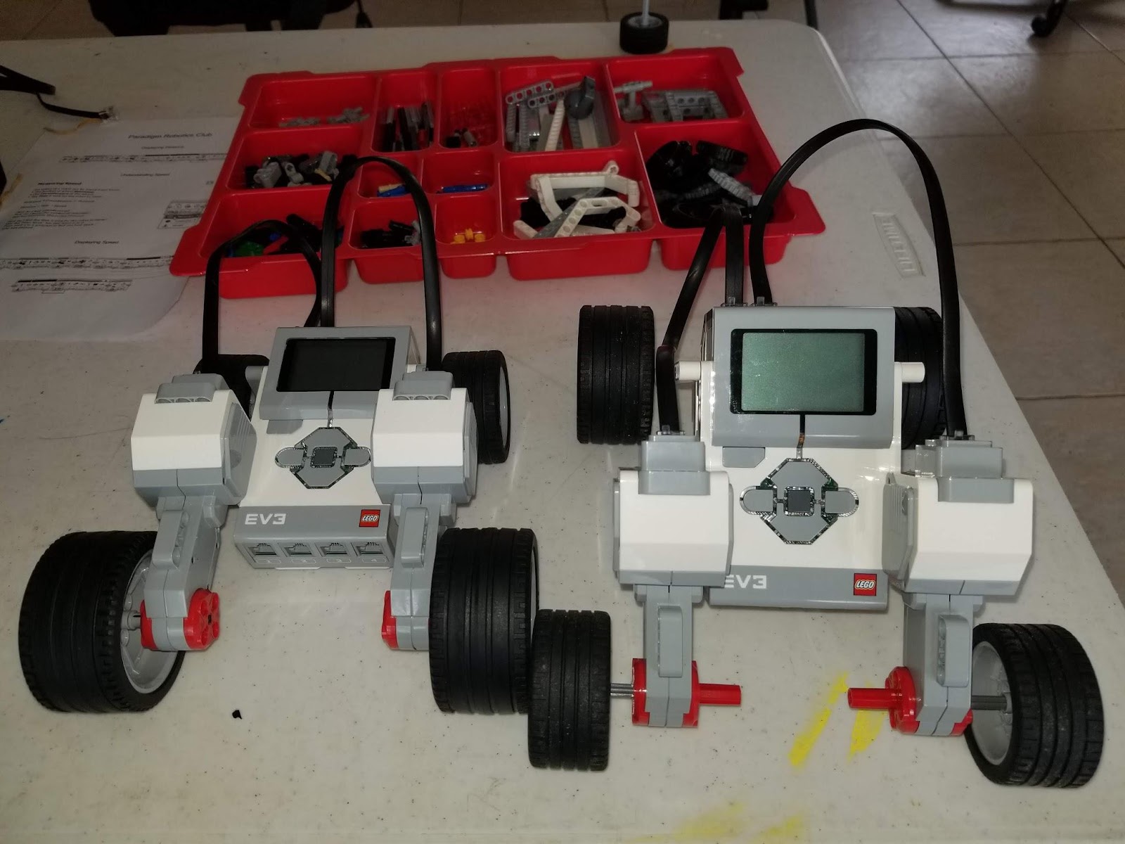
We first let the builders test their original robots on the incline to give us a baseline of the abilities of robots that were designed for other applications. We quickly pointed out that ALL of our robots were able to manage some degree of incline.  This gave us the opportunity to then introduce the key elements of succeeding in this challenge. We contrasted our previous designs with the variables of an effective design structure for this specific challenge. 
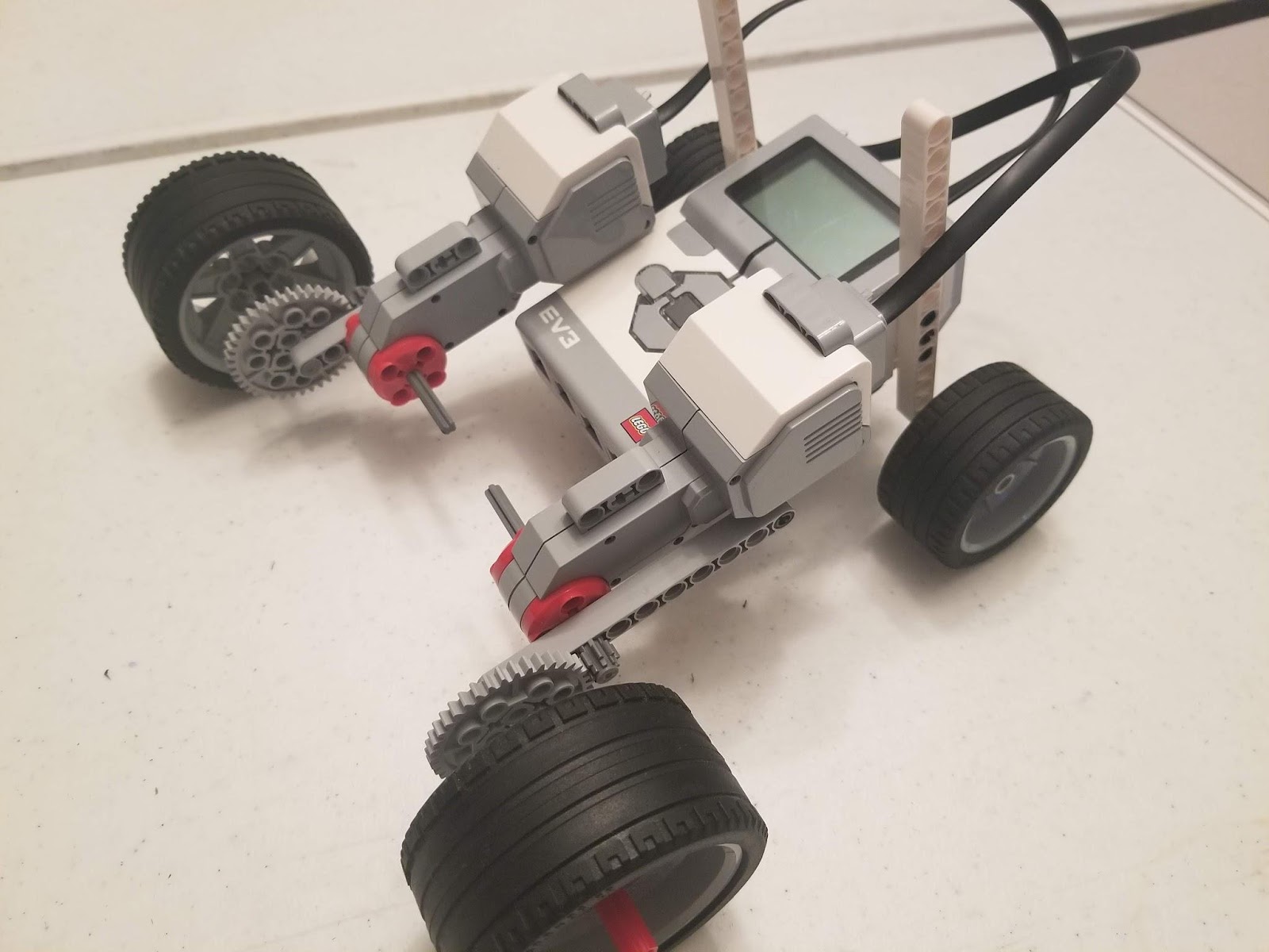
First, we watched a video on Gearing Up and Down and discussed the trade-off between speed and torque. After that, we quickly discussed the Center of Balance (COB) and how the combination of it with Weight Distribution would help us avoid tipping over AND not sliding on the surface of the incline. 

One builder quickly used the principles of Gearing Up to make a super fast robotic car. After having fun analyzing how this affected motor output, sound, and traction, we did the right thing and crashed it into everything we could. Then we tested it on the incline. The builder realized right away that we had traded off too much torque for speed when the wheels would not turn on the same incline as our initial trial. We reviewed the concept of Gearing Down to gain torque at the expense of speed and began to make some design changes. 

Other builders went through some of the growing pains of figuring out how to implement gears into their drive trains. We discussed different designs and also referred to the extraordinary book “Lego Mindstorms EV3 Idea Book” by Yoshihito Isogawa. This book has invaluable examples of mechanical setups that are useful for all kinds of robotics applications. 

We plan to continue in the cycle of Brainstorming, Building Prototypes, Testing, and Analyzing Results at our next meeting, March 29, 2019.


The Challenge Instructions
Ramp Climber

Design and build a car that can climb as steep a ramp as possible.
Engineers repeatedly test their creations and use the results to make improvements to their designs. As you test your car on the ramp, pay attention to what goes wrong–does the car veer to one side, flip over, slide? Noting how the car fails may help you decide what change to try next.

Materials needed
  • LEGO pieces for building a motorized one-motor or two-motor car.
  • Additional LEGO beams, wheels, and gears
  • Board for creating a ramp
  • Protractor or app for measuring the ramp’s angle of incline

Notes for the teacher
This activity can be done using MINDSTORMS EV3 or NXT, WeDo, BOOST, or Power Functions motors and battery packs.

To construct the ramp, you will need a sturdy board approximately one-meter long. To make the angle adjustable, you can support the top of the board on a bookshelf, moving the top from shelf to shelf to adjust the angle.

Encourage the students to make only one change at a time and then evaluate it. Many of the students will be tempted to implement several of their ideas at once. Point out to them that it will be much harder to determine the effect of each modification if they have made several changes between trials.

If the students reach a dead end in trying to improve the vehicle, help them to analyze the problems they are encountering. If the wheels slip, they may want to try a different type of tires. If the car stalls in one place, they may want to gear it down to increase torque. If the car tips backward, they may want to lower its center of gravity.

Torque enters into many aspects of this lab. First, the students can increase the torque of their motors by gearing down the cars. Second, increasing the wheel size decreases the force with which the wheel pushes against the ground since the torque of the motor is more-or-less constant and the distance to the point where the force is applied increases with the radius of the wheel. Third, the cars tend to veer sideways as the ramp gets steeper. Mounting the forward wheel(s) well in front of the heavy center part of the car will tend to counteract this tendency by producing a counter-torque.

Monday, March 4, 2019

Robotics Club Happenings!

What Have We Been Doing?


During the last two week's club meetings, we have been executing the Brainstorming and Building & Testing Prototype Stages of the Design Process.

Robot Builders figured out clever ways to bring wheeled locomotion to their robots while absorbing and applying the learned knowledge about the relationships of the circumference of wheels to distance traveled. While these terms are used in Geometry, in a traditional educational setting, here we applied multiple disciplines to achieve actual movement of a robot to a specific distance (4-feet).

Multiple Disciplines

In Geometry, one may measure the diameter of a two-dimensional circle, multiply by pi (3.14….) to learn the circumference of the circle. One may then use division to see how many rotations will be needed to reach a certain distance. However, in Engineering, one will also need to select the proper width, tread, and suitability of a tire to specific terrains to accomplish that distance. During the last two club meetings, Robot Builders quickly found out that calculations cannot be our only measure of understanding, but EXPERIENCE of what can go wrong on this plane of 3-dimensional reality is just as important as the academic discipline.


Once all teams were successful in propelling their robots exactly 4-feet, we then learned about the considerations of displaying the distance on their robots. This included understanding the different functions of the motor sensors that can potentially sense a 1-degree rotation of their axles, and how we can use math functions to translate that axle movement back into the distance. We also learned how to take that dynamic data and input it through “data lines” to our “text creation” programming blocks to be stitched together with the units of measure in “inches”. And finally, builders learned how to feed all of that text into the robot’s display for everyone to see.


Here is the sample code that we focused on, to learn the functionality of each block:


The Motor Control and Display blocks are in Green. The Yellow blocks are the Motor Sensor Controls. The Red blocks are the Mathematical Algorithm block and the Text Creator block.


Rotations * Circumference = Distance

Distance divided by Time = Speed

Next week, we will be learning about the variables associated with speed. The next club meeting is March 8, 2019. We will not have a club meeting on March 15, 2019 (this is Spring Break).

- Loren Marvin, Robotics Instructor

Wednesday, February 20, 2019

Robotics Club: February 15, 2019

Introductions

On February 15, 2019, the Robotics Club started by introducing new club members. Then we reviewed the lesson from our first meeting which included the first stages of the engineering design process (Define a Problem & Brainstorming) and the relationship between circumference and revolutions to distance moved. Then we applied this understanding by measuring the circumference differences between wheel sizes and how far they moved in one revolution. 

Related Vocabulary

circumference, speed, steering block, display block, revolutions, design, Applied Math, measure, wheel, motors, data wires, blocks, programming, control unit, distance, and commands

What did we cover & do?

  • Define Problem
  • Brainstorming
  • Building
The main parts we focused on relating to the first problem were the control unit, large and medium motors, data wires, wheels, and the rest of the Lego building blocks. Next, the students brainstormed and worked on their first prototypes.

By the end of the meeting, all the students built EV3 robot prototypes that will meet the design specifications stated in our problem. 

Next Robotics Meeting

During our next meeting, on February 22, 2019, the students will be introduced to the programming environment as well as the internal workings of the large EV3 motors. We are also going to cover how to display objects on the control unit. 

If we have time, we may work on converting their circumference measurements to revolution commands for the large motors that will get them the required one meter of distance.

- Loren Marvin, Robotics Instructor

Prototypes-in-Progress


Wednesday, February 13, 2019

Robotics Club: February 8, 2019

Introductions

On February 8, 2019, the Robotics Club re-started its second-semester meetings. The meeting was started by having the students Introduce themselves and share two important facts they would want others to know about them.


Engineering Design Process

The engineering design process is a series of steps that engineers follow when they are trying to solve a problem and design a solution for something; it is a methodical approach to problem-solving. 

After introductions, we discussed the concepts of the Engineering Design Process: Define the Problem, Research/Brainstorm, Draw/Design Solutions, Test/Record Date, and Communicate Results


Open-Ended Design Projects Versus Following Design Instructions


The club participants and I also talked about open-ended design projects vs. following design instructions.

Open-ended design in STEM has been shown to have a positive impact on retention, stimulates interest in engineering and enhances communication, team-building skills, and time management skills.


Last semester, students followed premade design instructions for robots that were designed for the specific purposes of the Lego Design team. This semester, students are using an open-ended design concept. At the beginning of each project, they work together to identify the goals and specifications for the project. Each project is designed to incorporate both aspects of technology that students have previous knowledge of and many aspects that they do not have knowledge of. This allows space to build structured lessons into the powerful format of individual creativity that must be used by each student to solve the Problem through their own Brainstorming, Designing, Building, and Testing phases of the process.

What did the students do?

During this first meeting, we defined our goals as Design, Build, and Test a robot that:
  1. Moves autonomously exactly 1 meter
  2. Uses at least 1 Motor
  3. Uses wheels for locomotion
  4. Displays the distance traveled on the robot’s screen

We covered how to translate basic robot controls (Turn Motor __ Revolutions) into real distances. This was done by measuring the circumference of the wheels that will be attached to the motors. We did these measurements together to master the skills. We used a couple of wheels, a string, and a ruler to measure the circumference. Then we proved through many trials that the circumference is equal to the distance traveled in 1 revolution.


Using this newfound knowledge will be valuable in the design and planning stages of club participants' solutions, along with other new knowledge and skills. We will also explicitly cover how to program the robot interface to display information gathered from the motors.  But FIRST…..We design!!

- Loren Marvin, Robotics Instructor


Our next meeting is February 15, 2019.